I recently owned a rode a 2012 Triumph Thruxton for one year after having ridden a 2008 Bonneville Black for 65,000 miles. During that year, I came to appreciate the footpeg and leg position setup of the Thruxton. So, having recently sold the Thruxton and completed the rebuild of the 2008 Bonneville, I decided to install rearsets on the Bonneville to be more like the Thruxton setup I had come to appreciate.
After some online research, I decided to purchase the Sato Racing Rearsets in black anodized aluminum to match my predominantly black Bonneville. These can be purchased from multiple sources including directly from Sato Racing or New Bonneville, Canyon Triumph and more.

Sato Racing Rearset Kit Parts, instructions and photos. All parts are aluminum or stainless steel.
In the end, I was able to make this kit conversion successfully. However, the instructions and photos are not complete or detailed enough for this to go smoothly. I had to do a lot of trial and error, online research and communication with Sato Racing to finally figure it all out. Here are photos of the finished installation.
 - left side footpeg and gearshift setup.")
Fully installed Sato Racing Rearset (black) – left side footpeg and gearshift setup.
 - right side footpeg and rear brake lever setup.")
Fully installed Sato Racing Rearset (black) – right side footpeg and rear brake lever setup.
In the days ahead, I will be taking these rearsets apart and creating step-by-step photos and descriptions of how it all goes together, and updating this page with that information.
Here are the official images from Sato Racing

Sato Racing Rearset for Bonneville – Left Side 1 – Note that there are 2 position holes the footpegs can be mounted in… the photo shows the peg mounted in the upper one, which I chose to use as well.

Sato Racing Rearset for Bonneville – Left Side 2

Sato Racing Rearset for Bonneville – Right Side 1

Sato Racing Rearset for Bonneville – Right Side 2
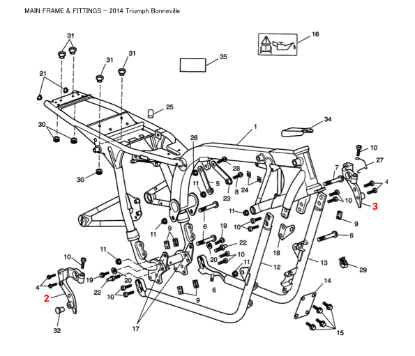
Triumph Bonneville Frame Parts Diagram
Another thing that was not clear from the instructions is that Bonneville frame parts #2 and #3 (Outriggers) stay on the bike.
Revealing the hidden areas
Here are some additional photos taken with the side covers removed, that may help those of you trying this conversion for the first time.
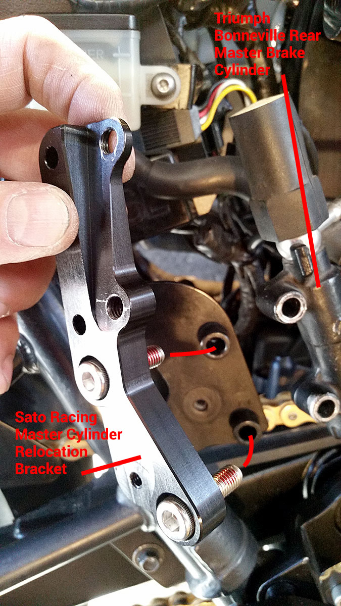
Rear brake master brake cylinder relocation bracket
The first thing that wasn’t clear to me was how the rear brake master cylinder relocation bracket mounts to the bike. The reason is that it is located behind the right side panel, and so you don’t see it in the Sato Racing instruction photos. The first photo below shows the right side panel removed, and the brake master cylinder unmounted (2 bolts). Here I am holding the relocation bracket in position with the two new SS bolts ready to insert into the existing master cylinder mounting holes.
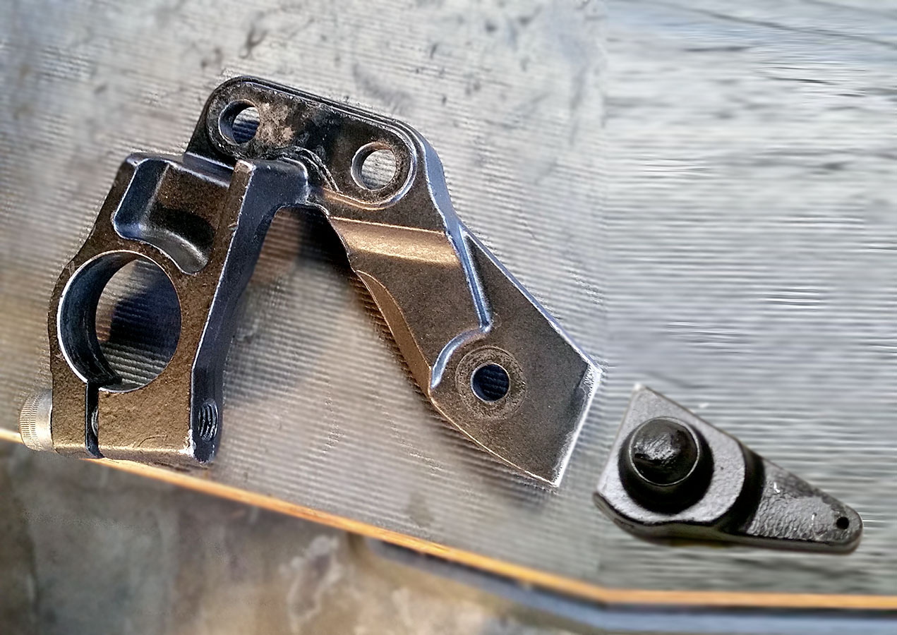
What the right side rear brake master cylinder relocation bracket looks like before being mounted on the original brake cylinder holes.
The next photo shows the relocation bracket mounted to the original master cylinder mounting bolt holes. Now it takes a bit of hose stretching to mount the master cylinder in the two holes at the top right of the relocation bracket. These holes are located within an angled plane that changes the angle of the master cylinder slightly.

Right side rear brake master cylinder mounting bracket close up with brake cylinder not mounted – this is not shown in Sato Racing photos or instructions.
Here we see the master cylinder relocation bracket mounted, from a slightly different angle.

Slightly different view of right side rear brake master cylinder mounting bracket close up with brake cylinder not mounted – this is not shown in Sato Racing photos or instructions.
Here we see the relocation bracket in place with the brake master cylinder mounted in a new position on the new bracket.

Right side rear brake master cylinder relocation bracket with master cylinder mounted in the new position, and connected to the rear brake foot lever.

Right side rear brake master cylinder relocation bracket closer view – with rear brake master cylinder shown in new position.
Here’s another right side view showing the big picture of how everything is oriented (covers removed).

Right side rear brake master cylinder relocation bracket with master cylinder mounted, side cover removed.
Right Side Rear Brake Rearset
This is Triumph Part #T2075061 called the Outrigger, RH. It is part #2 in the frame diagram above. I cut off the extension on my bike because I do not need the exhaust mounting hole.
Triumph part #T2075061 (Outrigger, RH) cutoff since I did not need the extension for my application.
Here is my RH Outrigger with the Sato Racing right side rearset mounted to it.

Right side rearset mounted over Part #2 (Outrigger) in the frame diagram above.
Here is the Right Side Rearset being attached with spacers to the RH Outrigger (looking down from top).

Right side rearset showing the spacers between rearset and Part #2.
This next photo shows how the Left Side Rearset attached to the Left Hand Outrigger, with spacers in between.
.")
Left side rearset showing the spacers between rearset and Part #3 (Outrigger, LH).